Geodesic and Goldberg Polyhedra Mathematics
Overview
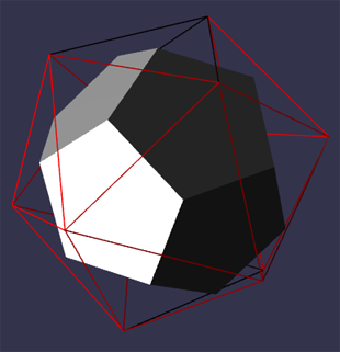
In this design we restrict both polyhedra to ones built from an icosahedron base. A Geodesic polyhedron is built from a number of equilateral triangles. A Goldberg polyhedron is the dual of a Geodesic one and vice versa. A dual of a polyhedron swaps faces for vertices and vertices for faces.
Fig 1 Icosahedron and its Dual
The simplest class of Geodesic polyhedra splits each face of an icosahedron into equilateral triangles.
Fig 2 Geodesic Polyhedron

Fig 3 Geodesic Polyhedron mapped to Sphere

More complex classes are formed by rotating, with restrictions, the isometric grid formed by the equilateral triangles that split each face.
Geodesic Classes
A regular icosahedron is formed from 20 primary equilateral triangles. Rather than rotating the underlying grid we demonstrate the classes by rotating a primary triangle on a fixed isometric grid.
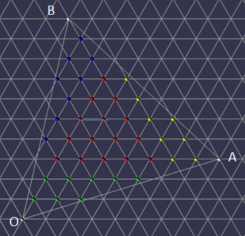
Rotations are formed by applying two positive integers m and n. From a fixed point O (0, 0) on the isometric grid form a point A (m, n) which is m horizontal units from O and n units along the positive gradient line. The primary triangle is formed with a point B such that OAB is an equilateral triangle. The Geodesic polyhedron so formed will be noted as GD(m, n) and its dual the Goldberg polyhedron as GP(m, n);
Fig 4 Creating a GD(5, 2) on Isometric Grid

Fig 5 Primary Triangle Grid Rotation 5, 2

There are three classes of these types of polyhedra
- Class I GD(m, 0)
- Class II GD(m, m)
- Class III GD(m, n) m ≠ n
For Class III GD(m, n) and GD(n, m) are reflections of each other as are GP(m, n) and GP(n, m). We only consider Class III GD(m, n) where m > n.
Geodesic Nets
Fig 6 Net of Icosahedron for GD(5, 2)

From the net we can see that while some of the triangular faces that will make up the Geodesic mesh lie in the plane of a primary triangle others will lie across adjacent primary triangles
Fig 7 Vertices of some triangular faces lie across adjacent primary triangles.

When the icosahedron is formed from the net these faces will not lie on any the plane of any primary triangle.
Building the Geodesic Polyhedron
There are two main steps to this:
- Grouping the vertices into three to form each face of the Geodesic polyhedron
- Positioning the vertices in 3D space
In order to achieve both of these we need to understand transformations on an isomorphic grid and how to match three facet vertices across the edges of a primary triangle. Using Fig 7 as a basis, we can then label each GD(m, n) vertex in a primary triangle using an isomorphic coordinate system and then use rotations of 60o of a primary triangle to match up vertices to form the triangular facets of an adjacent primary triangle.
Transformations on an Isomorphic Grid
In terms of the net all the GD(m, n) vertices lie on an isometric grid and we will need to rotate them 60o about given points. To understand how this is achieved we consider isometric vectors and their transformations.
The x axis is horizontal and the angle between the x axis and the y axis is 60o
Fig 8 Isometric Axis

The unit vector along the x axis is i⃗ and along the y axis is j⃗, the unit vector k⃗ = -i⃗ + j⃗which lies along the third line of an isometric grid is also useful.
Fig 9 Unit Vectors

Consider the position vector xi⃗ + yj⃗ its length |xi⃗ + yj⃗| = √(x2 + y2 + xy);. This is the result of applying the cosine rule to the triangle in Fig 10
|xi⃗ + yj⃗| = √(x2 + y2 + 2xycos(120o)); and cos(120o) = 0.5
Fig 10 Unit Vectors

Vector additions still hold xi⃗ + yj⃗ + ai⃗ + bj⃗ = (x + a)i⃗ + (y + b)j⃗
Luckily all our application needs only integer values for the vectors and rotations only multiples of 60o
Consider the rotation of the position vector xi⃗ + yj⃗ 60o about the origin O, where x and y are integers. The rotation about the origin can be R+ (counter clockwise purple to red) or R- (clockwise purple to blue) as in Fig 11
Fig 11 Rotation about the origin

R+(xi⃗ + yj⃗) = yk⃗ + xj⃗ = y(-i⃗ + j⃗) + xj⃗
= -yi⃗ + (x + y)j⃗
R-(xi⃗ + yj⃗) = yi⃗ - xk⃗ = yi⃗ - x(-i⃗ + j⃗);
= (x + y)*⃗ - xj⃗
Where S+ and S- are respectively counter clockwise and clockwise rotations of xi⃗ + yj⃗ 60o about a point ai⃗ + bj⃗
S+(xi⃗ + yj⃗, ai⃗ + bj⃗)
= R+((xi⃗ + yj⃗) - (ai⃗ + bj⃗)) + ai⃗ + bj⃗
= R+((x - a)i⃗) + (y - b)j⃗) + ai⃗ + bj⃗
= -(y - b)i⃗ + ((x - a) + (y - b))j⃗ + ai⃗ + bj⃗
= (a + b - *y)i⃗ + (x + y - a)j⃗
S-(xi⃗ + yj⃗, ai⃗ + bj⃗)
= R-((xi⃗ + yj⃗) - (ai⃗ + bj⃗)) + ai⃗ + bj⃗
= R-((x - a)i⃗ + (y - b)j⃗) + ai⃗ + bj⃗
= (x - a + y - b)i⃗ - (x - a)j⃗ + ai⃗ + bj⃗
= (x + y - b)i⃗ + (a + b - x)j⃗
Fig 12 Symmetry Rotations 0 o, 120o, -120o

We also need to consider rotations 120o and -120o about the center of the triangle OAB.
Let P have position vector xi⃗ + yj⃗ which after a rotation of 120o maps to P1 and after a rotation of -120o maps to P2
P1 = mi⃗ + nj⃗ - yi⃗ + xk⃗
= mi⃗ + nj⃗ - yi⃗ - xi⃗ + xj⃗
= (m - x - y)i⃗ + (n + x)j*⃗
P2 = -ni⃗ + (m + n)j⃗ - yk⃗ - xj⃗
= -ni⃗ + (m + n)j⃗ + yi⃗ - yj⃗ - xj⃗
= (y - n)i⃗ + (m + n - x - y)j⃗
Where RC+ is a rotation of 120o and RC- is a rotation of -120o about the center of OAB
RC+(xi⃗ + yj⃗) = (m - x - y)i⃗ + (n + x)j*⃗
RC-(xi⃗ + yj⃗) = (y - n)i⃗ + (m + n - x - y)j*⃗
Match Vertices Across Edges of a Primary Face
We can label the face and vertices for each primary triangle as shown in the net for Fig 13. Taking OA as the base, OB as the left edge and AB as the right edge of each face; every face has a face on its left, FL, right, FR, and base FB
Fig 13 Labelled Net

Depending on the position of the face the vertex alignment differs as can be seen in Fig 14.
Fig 14 Face and Edge Relationships

Since F shares edges with FR, FL and FB any matching of GD(m, n) vertices across the edges of F can be dealt with by considering the counter clockwise rotations of various permutations of F, FR, FL or FB around the vertices, O, A or B, as shown in red in Fig 14. The 30 possible edges are all covered by the table below.
| From Face | To Face | About | From Face | To Face | About | |
|---|---|---|---|---|---|---|
From Face 0 | To Face 1 | About B | From Face 10 | To Face 0 | About O | |
From Face 1 | To Face 2 | About B | From Face 11 | To Face 1 | About O | |
From Face 2 | To Face 3 | About B | From Face 12 | To Face 2 | About O | |
From Face 3 | To Face 4 | About B | From Face 13 | To Face 3 | About O | |
From Face 4 | To Face 0 | About B | From Face 14 | To Face 4 | About O | |
From Face 5 | To Face 10 | About O | From Face 15 | To Face 19 | About B | |
From Face 5 | To Face 14 | About A | From Face 15 | To Face 5 | About A | |
From Face 6 | To Face 11 | About O | From Face 16 | To Face 15 | About B | |
From Face 6 | To Face 10 | About A | From Face 16 | To Face 6 | About A | |
From Face 7 | To Face 12 | About O | From Face 17 | To Face 16 | About B | |
From Face 7 | To Face 11 | About A | From Face 17 | To Face 7 | About A | |
From Face 8 | To Face 13 | About O | From Face 18 | To Face 17 | About B | |
From Face 8 | To Face 12 | About A | From Face 18 | To Face 8 | About A | |
From Face 9 | To Face 14 | About O | From Face 19 | To Face 18 | About B | |
From Face 9 | To Face 13 | About A | From Face 19 | To Face 9 | About A |
Table 1
 
We can see that a rotation about B aligns edge AB and OB, about O aligns edge OB and OA and about A aligns OA and BA.
We now consider obtaining the three vertices for the edge overlapping facets in more detail. We start with a rotation about B
Fig 15 Rotation of Primary Triangle about the B for - Left GD(5, 2), Right (GD(6, 3))

Consider a primary triangle OAB as in Fig 15. For triangle OAB take O as the origin of the isometric axes then each vertex (red sphere) can be given (x, y) coordinates. For each y there is a minimum (blue marker) and maximum (green) value of x that belong to OAB. Rotating OAB 60o counter clockwise about B the minimum x map to the orange markers in the rotation. As you can see in Fig 15 example there is overlap of maximum and minimum markers at the primary triangle vertices. For GD(m, n) when n is a factor of m then the maximum x (green) of OAB coincide with the rotated minimum x (orange) for some facet vertices as well as at the primary triangle vertices.
We can also see that rows contain either one or two rotated minimums.
Fig 16 Facet Overlap Vertices

In Fig 16 we can see that there are three types of rotated minimum vertices 0, 1, 2 that produce facets that overlap the edge. Each of these points can be associated with two facet triangle, one that is up (light grey) and one down (dark grey).
For all facet vertices xi⃗ + yj⃗ of a primary triangle OAB of GD(m, n) let Mmax(y) be the point with maximum x value and Mmin(y) the point with minimum x value for row y.
Let P = xpi⃗ + ypj⃗ be the position vector of a rotated minimum xi⃗ + yj⃗ = Mmin(y).
When P = Mmax(yp) the up and down facets lie inside the primary triangle are are thus ignored in creating ovelapping facets.
For an up facet When P is of type 0 and 1 the facet (light grey) has vertices P, Mmax(yp - 1), P + i⃗ - j⃗
When P is of type 2 the facet (light grey) has vertices P, Mmax(yp - 1) - i⃗, Mmax(yp - 1)
For a down facet When P is of type 0 the facet (dark grey) has vertices P, Mmax(yp), Mmax(yp - 1)
When P is of type 1 the facet (dark grey) has vertices P, P - i⃗, Mmax(yp - 1)
When P is of type 2 the facet (dark grey) has vertices P, Mmax(yp), Mmax(yp - 1) - i⃗
This range of vertex triples forms all the overlapping facets.
Considering Fig 15 these position vectors are all relative to the origin O of primary triangle F. However for facet vertices in FR we need the position vectors of these vertices to be relative to the origin O of FR. Rotating FR 60o clockwise will return FR to the primary triangles position as in Fig 4
For each vertex in the triples based on P we just need to apply S-. Since S-(S+) is the identity S-(P, B) = xi⃗ + yj⃗
For xi⃗ + yj⃗
Type 1 occurs when P.j⃗ = S+(Mmin(y + 1);, B).j⃗
Type 2 occurs when P - j⃗ ≠ Mmax(yp - 1)
Otherwise P is of type 0.
P = S+(xi⃗ + yj⃗, B)
= S+(xi⃗ + yj⃗, -ni⃗ + (m + n)j⃗)
= (-n + m + n - y)i⃗ + (x + y + n)j⃗
= (m - y)i⃗ + (x + y + n)j⃗
P + i⃗ - j⃗ = (m - y)i⃗ + (x + y + n)j⃗ + i⃗ - j⃗
= (m - (y - 1))i⃗ + (x + (y - 1) + n)j⃗
= S+(xi⃗ + (y - 1)j*⃗, B);
P - i⃗ = (m - y)i⃗ + (x + y + n)j⃗ - i⃗
= (m - (y + 1))i⃗ + (x - 1 + (y + 1) + n)j⃗
= S+((x - 1)i*⃗ + (y + 1)j*⃗, B);
If follows that the overlapping facet vertex triples are given by
| P Type | Triangle | Vertex Triple |
|---|---|---|
P Type 0, 1 | Triangle Up | Vertex Triple MFRmin(y), MFmax(yp - 1), MFRmin(y - 1) |
P Type 2 | Triangle Up | Vertex Triple MFRmin(y), MFmax(yp - 1) - i⃗, MFmax(yp - 1) |
P Type 0 | Triangle Down | Vertex Triple MFRmin(y), MFmax(yp), MFmax(yp - 1) |
P Type 1 | Triangle Down | Vertex Triple MFRmin(y), MFRmin(y + 1), Mmax(yp - 1) |
P Type 2 | Triangle Down | Vertex Triple MFRmin(y), MFmax(yp), MFmax(yp - 1) - i⃗ |
Table 2
A rotation about O is as in Fig 17
Fig 17 Rotation OAB 60o about O

This can also be achieved by rotating the diagrams in Fig 15 120o counter clockwise as in Fig 18
Fig 18 Rotation Fig 15 120o about O

Hence applying a rotation of 120o to the values in Table 2 will produce the correct vertex isometric positions for the overlapping facets of edges OA and OB
A rotation about A is as in Fig 19
Fig 19 Rotation OAB 60o about A and translation

This can also be achieved by rotating the diagrams in Fig 15 -120o counter clockwise and translating -mi⃗ - nj⃗ as in Fig 20
Fig 20 Rotation Fig 15 -120o about A and translation

Hence applying a rotation of -120o about A to the values in Table 2 followed by a translation of -mi⃗ - nj⃗ will produce the correct vertex isometric positions for the overlapping facets of edges OA and AB.
Facet Isometric Coordinates
For each facet vertex that lies on on within the primary triangle we determine the isometric coordinates (x, y). When constructing the primary triangle for GD(m, n) O is (0, 0), A is (m, n) and B is (-n, m + n) these are the white vertices in Fig 21
Fig 21 Internal Facet Vertices

The red vertices lie on the maximum equilateral triangle CDE, that can be drawn wholly inside OAB along grid lines. The bottom left red vertex lies on the intersection of the y axis and the line through A parallel to the x axis and so has iso-coordinates (0, n).
Fig 22 Rotating (x, y) 0, 120o, -120o
Therefore by rotational symmetry
D = RC+(0, n) = (m - n, n) and
E = RC-(0, n) = (0, m)
Now consider the green vertices, they all lie on triangles similar to OCA as in Fig 23 and note that OA = n and CA = m
Fig 23 Green Vertices

Let F be the point (0, y) with y < n and G the point (x, y). Let H be the point where the extended line through FG meets OA. It follows that x ≤ FH. Note that
Fig 24 Similar Triangles

Triangles OCA and OFH are similar and so
FH = OF
CA OC
and so
FH = y * (m / n) and since x ≤ FH
x ≤ y * (m / n);
The green vertices all lie on the iso-grid and so are all points (x, y) with integer values for x and y where
0 < y < n and 0 ≤ x ≤ y * (m / n); Using rotation symmetry and rotating about the center of OAB 120o and -120o gives the yellow and blue vertices.
Fig 25 Facet vertices along edges when m and n ≠ 0 have factors in common and n ≠ 0

Any facet vertices lying on an edge of a primary triangle will have the same position as that on a matched edge.
When n = 0, there is no rotation and there are m - 1 shared positions along each edge between the vertices.
When n ≠ 0, let g be the HCF (highest common factor) of m and n. When n = 1 there are no shared positions along each edge between vertices. When n > 1 let m1 and n1 be such that m = gm1 and n = gn1 then the number of shared positions between the vertices along one edge is g - 1.
Along OA they occur at m1i⃗ + n1j*⃗, 2m1i⃗ + 2n1j*⃗, ......, (g - 1)m1i⃗ + (g - 1)n1j*⃗.
Along AB at RC+(m1i⃗ + n1j*⃗), RC+(2m1i⃗ + 2n1j*⃗);, ......, RC+((g - 1)m1i⃗ + (g - 1)n1j*⃗).
Along BO at RC-(m1i⃗ + n1j*⃗), RC-(2m1i⃗ + 2n1j*⃗);, ......, RC-((g - 1)m1i⃗ + (g - 1)n1j*⃗).
Cartesian Coordinates
Fig 26 Cartesian Coordinates

Fig 26 shows that the cartesian coordinates of a point with position iso-vector xi⃗ + yj⃗
has cartesian coordinates (x + 0.5y, 0.5√3y)
Mapping Primary Triangle to Icosahedron Face
Fig 27 Primary Triangle Mapping to Icosahedron Face

Let OAB be an equilateral triangle with a Cartesian frame of reference with units vectors u⃗ and v⃗ along the X and Y axes respectively and i⃗ and j⃗ the usual iso-vectors. O1A1B1 and the frame of reference X1Y1 are formed by a rotation and scaling of OAB and XY in 3D space with u1⃗ and v1⃗ and i1⃗ and j1⃗ the corresponding Cartesian and iso Vectors.
Let P be any point with cartesian position vector xu⃗ + yv⃗. Let d be the scaling of O1A1B1 to OAB. The corresponding point P1 to P with have position vector xdu⃗1 + ydv⃗1.
In iso_vectors OA = mi⃗ + nj⃗ and OB = -ni⃗ + (m + n)j⃗ and so in Cartesian vectors
OA = (m + 0.5n)u⃗ + 0.5√3nv⃗ and
OB = (0.5(m + n) - n)u⃗ + 0.5√3(m + n)v⃗ = 0.5(m - n)u⃗ + 0.5√3(m + n)v⃗
(m + 0.5n)OB = (m + 0.5n)(0.5(m - n))u⃗ + 0.5√3(m + n)(m + 0.5n)*uv⃗
(0.5(m - n))OA = (m + 0.5)(0.5(m - n))u⃗ + 0.5√3n(0.5(m - n))v⃗
(m + 0.5n)OB - (0.5(m - n))OA = 0.5√3((m + n)(m + 0.5n) - n(0.5(m - n)))v⃗
(2m + n)OB - (m - n)OA = √3(m2 + 0.5n2 + mn + 0.5mn - 0.5mn + 0.5n2)v⃗
(2m + n)OB - (m - n)OA = √3(m2 + n2 + mn)v⃗
from which we can find v⃗ and then u⃗ in terms of OA and OB.
Since O1A1 = mdi1⃗ + ndj1⃗ and
O1B1 = -ndi1⃗ + (m + n)dj1⃗
we can use this method to find v1⃗ and then u1⃗ in terms of O1A1 and O1B1 so that we can determine P1.
For example when finding v1⃗ the coefficient of O1B1 will be
d(m + n)
d2√3(m2 + n2 + mn)
=
(m + n)
d√3(m2 + n2 + mn)
We also note that m2 + n2 + mn = l2, where l is the length of OA.
Doing the calculations for v1⃗ and for u1⃗ the coefficients of O1A1 and of O1B1 all contain the common multiplier 1 / dl2.
Since xu⃗ + yv⃗ in OAB maps to xdu⃗1 + ydv⃗1 in O1A1O1B1 and d / dl2 = 1 / l2 when it comes to coding we can calculate constant coefficients just once and rather than calculating u⃗ and v⃗ as unit vectors calculate them as vectors scaled by d, for example
v⃗ = ((2m + n)O1B1 - (m - n)O1A1) / l2√3