Adding a Roof to a House Built from Plans
For any house there is a range of different types of roof that can be added and so there is no automatic way to use the footprint of a house to build a roof directly. However with a little bit of manual design there are methods that can complete the build. Here we present two ways to design and create a hip roof. The example used is based on the design and coding of this house.
Please note that some functions used in this project uses Earcut, so, in non playground projects, you will have to add a reference to their cdn or download their npm package
Design Whole Roof
In this case the rise, or roof height, is the same for all sections of the roof.
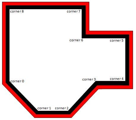
The footprint for the house defines the inner walls of the house, from which the data for the outer walls is calculated. A roof overhangs the the outer walls. The footprint of the roof, or roofprint, defines the corners of this overhang. In Fig 1 the black area shows the thickness, or ply of the house walls and the red the overhang of the roofprint.
Fig 1
Since in creating the house the ply, house height and the footprint corners have already been created they are used to create the roofprint, as in
var overhang = 0.2;var overlap = ply + overhang;var wholeRoofprint = roofprint(corners, overlap, height);
The function roofprint returns a list of Vector3 representing the corners of the roof floor in counter clockwise order.
Using the roofprint the floor of the roof (or top ceiling) can be added as a mesh.
Plan of Roof
Though it is possibly more accurate to use the roofprint as a guide to a plan for the roof it is probably easier (in terms of coordinates) to use the original footprint. All you need to do is draw, in a plan diagram, the planes of the roof. An apex is a highest point on the roof where planes meet. The plan diagram in Fig 2 shows the floorprint corners numbered C0, C1, C2 etc and the apexes numbered in sequence using A0, A1 etc. Fig 2 is drawn to scale based on the original base data.
Fig 2

var baseData = [-3, -2, -1, -4, 1, -4, 3, -2, 5, -2, 5, 1, 2, 1, 2, 3, -3, 3];
The red dash lines showing the axes.
From the diagram the roof apex data can be read off and the coordinate pairs placed in the array in sequence order. First pair is from A0, the second from A1 etc.
var roofApexData = [0, -2, 0, -0.5, 0, 2, 4.5, -0.5];
This data the needs to be turned into an array, apexes for example, of Vector2 which will be used as the second parameter of the roof function.
var apexes = [];for(var i = 0; i < roofApexData.length / 2; i++) {apexes.push(new BABYLON.Vector2(roofApexData[2 * i], roofApexData[2 * i + 1]))}
Each roof plane can be described using the corner and apex labels. The planes should be draw so that they are described with either 3 or 4 labels. Each plane is set as an array using the labels in a counter clockwise order with corner labels coming first. Remember that the corner labels are already in counter clockwise order. An array of planes is then formed containing all the plane data arrays.
var planes = [["C0", "C1", "A0"],["C1", "C2", "A0"],["C2", "C3", "A0"],["C3", "A1", "A0"],["C3", "C4", "A3", "A1"],["C4", "C5", "A3"],["C5", "C6", "A1", "A3"],["C6", "C7", "A2", "A1"],["C7", "C8", "A2"],["C8", "C0", "A0", "A2"]]
The roof function can then be applied to produce the sections or planes of the roof.
This takes the parameters as shown
roof(roofprint, apexes, planes, rise, height, uvbase)
The rise is the distance from the roof floor to an apex, the height is the height of the house.
The roof function creates uv values for each plane based on the size of the plane. So a plane that is twice as big as another will have double the uv values. For this to work the parameter uvbase has to larger than the maximum width and height of all the planes. As a rule of thumb use a value about the width (horizontal) of the largest plane.
The roof function creates the mesh of the roof.
In the example the roof mesh is built using
var roofSection = roof(wholeRoofprint, apexes, planes, 2, height, 5.6);
Design Roof In Sections
When you want different parts of the roof to have different heights then although it is possible to choose suitable apexes and planes it is much more difficult to determine the apex where a low roof meets the plane of a higher roof. For example in Fig 3 it is possible to calculate the x coordinate of apex A using 3D vector geometry.
Fig 3

The simplest solution however is to use values that extend the small roof into the large roof.
Following this method and using the original floor plan the plan for the lower roof section will cover the red area as in Fig 4
Fig 4

The help prevent Z fighting the plan for the higher roof will be reduced so that parts of it will fall inside the lower roof.
The plan drawing for the main roof is now as in Fig 5 and for the smaller roof as in Fig 6
Fig 5

Fig 6

Specific corners to be used by the roofprint function have to be created for the main and the small roof. The original corners are used to create the whole roofprint in order to construct the roof floor.
var wholeRoofprint = roofprint(corners, overlap, height);var mainRoofprint = roofprint(mainCorners, overlap, height);var smallRoofprint = roofprint(smallCorners, overlap, height);var ceiling = roofFloor(wholeRoofprint);
Apex arrays has to be formed for both the main and small roof
var apexes = [];for(var i = 0; i < roofApexData.length / 2; i++) {apexes.push(new BABYLON.Vector2(roofApexData[2 * i], roofApexData[2 * i + 1]))}var smallApexes = [];for(var i = 0; i < smallRoofApexData.length / 2; i++) {smallApexes.push(new BABYLON.Vector2(smallRoofApexData[2 * i], smallRoofApexData[2 * i + 1]))}
In the same way two plane arrays are needed, on for each roof
var planes = [["C0", "C1", "A0"],["C1", "C2", "A0"],["C2", "C3", "A0"],["C3", "C4", "A1", "A0"],["C4", "C5", "A1"],["C5", "C0", "A0", "A1"]]var smallPlanes = [["C0", "C1", "A1", "A0"],["C1", "C2", "A1"],["C2", "C3", "A0", "A1"]]
Then ,finally, both roof sections can be created
var roofSection = roof(mainRoofprint, apexes, planes, 2, height, 5.1);var smallRoofSection = roof(smallRoofprint, smallApexes, smallPlanes, 2, height - 1, 5.1);